Registers
- There are 8 8-bit general-purpose registers, named
r0throughr7.- Just like MIPS,
r0is special - reading it always gives 0 and writing to it does nothing.
- Just like MIPS,
- There is the 8-bit program counter (PC).
- Last there is the 16-bit display (DISP) used to display numbers, which is writable with the
putinstruction.
Memory
This is a Harvard (2-memory) architecture. This allows us to implement it as a single-cycle machine.
The instruction memory is a word-addressed read-only memory with 8 address bits and 22 data bits. Unlike MIPS, the instruction memory is not byte-addressed. Instead, each address holds 1 instruction, meaning the memory can hold 256 instructions. This also means that the “next instruction” is at PC + 1, not PC + 4.
The data memory is a byte-addressed RAM with 8 address bits and 8 data bits. This memory can hold 256 8-bit bytes.
Instruction format
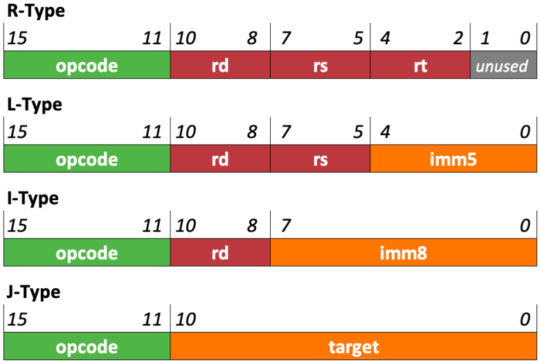
cpu2261 instructions are 22 bits long. There is only one instruction format.
- The
opcodefield is 5 bits, which is enough to encode up to 32 different instructions. - The
immfield is an 8-bit immediate. - The
rd,rs, andrtfields hold register numbers.- So if
rd == 4, then that meansr4.
- So if
The cpu2261 instruction set
- The Mnemonic column shows how the instruction is written.
- The Operation column shows how the instruction works. That’s what you implement!
- The
<-means “store the value on the right into the thing on the left.”- it’s like an assignment operator in a programming language, but..
- if there are multiple
<-operators in one instruction, they all happen simultaneously.
a : bmeans “the bits ofaconcatenated with the bits ofb.”x[4:0]or whatever means “bits 4 through 0 (the lowest 5 bits) of x”. It’s like you’re taking a “slice” of the value.- You can use a Splitter or a Bit Extender to do this.
REG[x]means “the register in the register file whose number is given by x.”RAM[x]means “the value in RAM at memory address x.”
Basic instructions
The tutorial walks you through implementing these instructions so I won’t say much here.
| Opcode | Mnemonic | Operation |
|---|---|---|
00000 |
hlt |
disable PC register and turn on HALT LED |
00001 |
put rs, rt |
display <- REG[rs] : REG[rt] |
00010 |
li rd, imm |
REG[rd] <- imm |
00011 |
mov rd, rs |
REG[rd] <- REG[rs] |
ALU operations
Both shr and sri use logical (unsigned) right shifts.
The not instruction does not use rs or REG[rs] at all. It does bitwise NOT on the second input to the ALU.
| Opcode | Mnemonic | Operation |
|---|---|---|
00100 |
add rd, rs, rt |
REG[rd] <- REG[rs] + REG[rt] |
00101 |
sub rd, rs, rt |
REG[rd] <- REG[rs] - REG[rt] |
00110 |
and rd, rs, rt |
REG[rd] <- REG[rs] & REG[rt] |
00111 |
or rd, rs, rt |
REG[rd] <- REG[rs] | REG[rt] |
01000 |
xor rd, rs, rt |
REG[rd] <- REG[rs] ^ REG[rt] |
01001 |
not rd, rt |
REG[rd] <- ~REG[rt] |
01010 |
shl rd, rs, rt |
REG[rd] <- REG[rs] << REG[rt][2:0] (see below) |
01011 |
shr rd, rs, rt |
REG[rd] <- REG[rs] >>> REG[rt][2:0] (see below) |
01100 |
adi rd, rs, imm |
REG[rd] <- REG[rs] + imm |
01101 |
sbi rd, rs, imm |
REG[rd] <- REG[rs] - imm |
01110 |
ani rd, rs, imm |
REG[rd] <- REG[rs] & imm |
01111 |
ori rd, rs, imm |
REG[rd] <- REG[rs] | imm |
10000 |
xri rd, rs, imm |
REG[rd] <- REG[rs] ^ imm |
10001 |
sli rd, rs, imm |
REG[rd] <- REG[rs] << imm[2:0] (see below) |
10010 |
sri rd, rs, imm |
REG[rd] <- REG[rs] >>> imm[2:0] (see below) |
The not instruction does not use rs or REG[rs] at all. It does bitwise NOT on the second input to the ALU. If you followed the directions in lab 7, your ALU already does this correctly.
Notes on shifting:
- For all the shift instructions (
shl,shr,sli,sri), if you followed the directions in lab 7, your ALU already gets the least significant bits of the shift distance; you don’t have to do anything else to make it work. - Both right-shift instructions (
shr,sri) use>>>which is logical (unsigned) right shift.
Memory access
| Opcode | Mnemonic | Operation |
|---|---|---|
10011 |
ld rd, [rs+imm] |
REG[rd] <- RAM[REG[rs] + imm] |
10100 |
st [rs+imm], rt |
RAM[REG[rs] + imm] <- REG[rt] |
When implementing these, think to yourself: do you really need another component to do the addition for the memory address? ;) (Remember the interconnect slides…)
Jumps
| Opcode | Mnemonic | Operation |
|---|---|---|
10101 |
j imm |
PC <- imm |
10110 |
jal rd, imm |
REG[rd] <- PC + 1 see below!PC <- imm |
10111 |
jr rs |
PC <- REG[rs] |
Two important things about jal:
- It works a little differently than in MIPS. You give it the register that you want the return address to be put into. So
jal r7, fwill user7as the “ra” register. - Don’t forget that it writes to the register file. A really common mistake is to forget to write-enable the register file for
jal!
Branches
All conditional branch comparisons are to be done using signed arithmetic. That means any Comparator component you use must be set to do signed (“2’s complement”) comparisons, or else certain tests will break!
| Opcode | Mnemonic | Operation |
|---|---|---|
11000 |
blt rs, rt, imm |
if(REG[rs] < REG[rt]) PC <- PC + imm; else PC <- PC + 1; |
11001 |
bge rs, rt, imm |
if(REG[rs] >= REG[rt]) PC <- PC + imm; else PC <- PC + 1; |
11010 |
beq rs, rt, imm |
if(REG[rs] == REG[rt]) PC <- PC + imm; else PC <- PC + 1; |
11011 |
bne rs, rt, imm |
if(REG[rs] != REG[rt]) PC <- PC + imm; else PC <- PC + 1; |
(opcodes 11100 through 11111 are unused.)