From now on, code style will be graded.
Your programs are getting bigger and the grader(s) need to be able to read them without clawing their eyeballs out. See the style guide for examples of good code style.
You are not required to use “Java-style” indentation, and comments are not required but are encouraged. At the very least, you code should be:
- indented as shown in the “Indentation” section. Remember: tab key, not space bar.
- using comments to visually separate functions (e.g. a
#-----------line)
Failure to use proper style can cause you to lose points from now on.
In this lab, you’ll be using arrays, functions, and for loops. You’ll also get a taste of that “top-down design” I talk about in class.
What will this program do? It will let you place tiles on a tilemap.
What?
You don’t know what a tilemap is? Oh, okay.

What the heck is a tilemap?
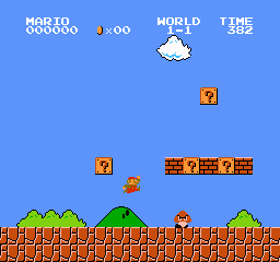
Think of real tiles you see on floors or walls. Let’s just restrict it to square tiles in a grid pattern, like the image on the right. You can put patterns on the tiles, and you can then put multiple tiles together to create an image.
In computer graphics, a tilemap is a grid of square images. Each grid square can be one of multiple different images, identified by number (e.g. “the tile at row 6 column 4 is image 9”).
This is a pretty old-fashioned way of doing graphics on computers, but it has some nice advantages:
- it takes up way less memory than the framebuffer that you used last time to draw pixels onscreen
- it only has to remember the tile number for each grid square, instead of the color of every single pixel
- it’s very quick to change large parts of the tilemap
- it automatically draws the images to the screen so you don’t have to do it every frame
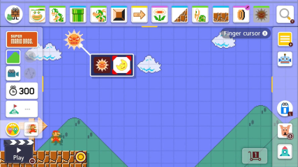
In old computers this was used originally to put text onscreen: one character per tile. But pretty soon, people started using this to put graphics onscreen, and through the 1980s, 1990s, and even into the 2000s, many home computers and video game consoles had support for tilemap-based graphics. This style of graphics lives on in video games even today, but in software form. (Ever play Mario Maker?)
0. Getting Started
Here is the include file for this lab. Just like lab 5:
- download it and put it in a folder for lab 6
- make a new file in MARS
- save it in the same folder as the include file as
abc123_lab6.asmwhereabc123is your username- your username is your default pitt email address without the @pitt.edu
- not your custom email address
- your username looks like three letters followed by one or more digits
- your username is your default pitt email address without the @pitt.edu
- copy and paste this code into your
_lab6.asmfile, and put your name and username in the comments at the top
# YOUR NAME HERE
# YOUR USERNAME HERE

.include "lab6_include.asm"

.data
	running: .word 1
.text

.global main
main:
print_str
I’ve made it even easier to print strings for this lab. All you have to do now is:
print_str "hello, world!\n"
or whatever. You can put this anywhere, and it will not mess up any registers. So you can use it for “debug prints” as much as you like. (The lstr macro from lab 5 is still available too, if you want it.)
1. main and load_graphics
In class we talked (or, will talk) about “top-down design” and “stubbing out” functions. Well that’s what we’re gonna do. We’re going to write our main function to call a bunch of other functions, then stub those functions out, and we’ll end up with a program that does nothing but has a bunch of things that we can work on in order.
main
void main() {
    // set up everything
    display_init();
    load_graphics();
    load_map();

    // main loop
    do {
        check_input();
        draw_cursor();
        display_finish_frame();
    } while(running != 0);

    // do syscall 10 here!!
}
The pseudocode for main is on the right. Write your main function following it. Notes:
- Remember that the MIPS equivalent of a function call like
display_init()isjal display_init. No parentheses. - A
do-whileloop is super simple: a label for thedo, and thewhileis a branch. - The
runningvariable is already declared for you up in the.datasegment.- It’s a variable, so you have to load it. Load it immediately before the branch, not somewhere else.
- Read the comment at the end - you have to do syscall 10 after the loop.
- Otherwise, when the loop ends, the CPU will just “go to the next line” and start running whatever function is declared after
main!
- Otherwise, when the loop ends, the CPU will just “go to the next line” and start running whatever function is declared after
If you try to assemble your code now, it won’t work. That’s because you’re calling multiple functions that don’t exist yet. Let’s fix that.
Stubbing out functions
To get your program assembling, let’s stub out the functions that don’t exist.
Never put new functions before main. main should always be the first function you see.
-
After
main, let’s stub outload_graphics. You start a function by making a comment to visually separate it from the previous function, like the# -----below. Then, you write the name as a label; and finally it ends withjr ra. So:# this is the end of main # for the love of god don't copy and paste this comment into main, I'm # just putting it here for illustrative purposes li v0, 10 syscall # --------------------------------------------------- load_graphics: jr ra -
Do the same thing again (as in, copy and paste what you just wrote and change the labels) for the
load_map,check_input, anddraw_cursorfunctions. You should now have something like:# --------------------------------------------------- load_graphics: jr ra # --------------------------------------------------- load_map: jr ra # --------------------------------------------------- # ...etc... - Assemble. It should now work.
- Open the display, connect it, and run. It should do… nothing.
- Well, it’s doing something. It’s looping infinitely.
- You have to hit the
 stop button to stop the program.
Important: If your program stopped on its own and you saw -- program is finished running -- in the messages, your do-while loop is not working right. Fix it now, before you continue. (You can put a test print like print_str "a" in the loop to make sure it prints that over and over. Remove that print when you’ve confirmed it works.)
load_graphics
Right now, the images we want to put on the display are in the data segment. Go look in lab6_include.asm for the tilemap_gfx and sprite_gfx arrays starting around line 117. There they are!
But the display can’t see those. We have to copy the graphics to specific locations in the display’s memory so it can see them. There are two functions that do that: display_load_tm_gfx to load tilemap (tm) graphics, and display_load_sprite_gfx to load sprite graphics. (We’ll talk about sprites.)
Here’s what you need to do in your load_graphics function. “Inside” load_graphics means “between the load_graphics: label and the jr ra.”
- call
display_load_tm_gfx(tilemap_gfx, 0, 4)- that’s a function call with three arguments.
- you have to put the values in the argument registers before the call. So it breaks down like:
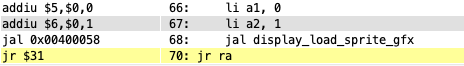
a0 = tilemap_gfx; // use la for this a1 = 0; a2 = 4; display_load_tm_gfx(); - call
display_load_sprite_gfx(sprite_gfx, 0, 1)the same way- sorry for the huge text, everyone misses this step
Alright, now assemble and run. You should see…
Nothing? You see nothing? Just a black screen? Hmmmmm. That’s not right!
Intermission: diagnosing control flow issues
I know what’s wrong here, but let’s learn some techniques you can use to figure out where things are going wrong.
Print debugging, the old standby
Since you have the print_str macro, you can put some prints in your program to see where it’s going. Try putting some prints in main like this:
main:
    jal display_init
    print_str "display initialized\n"
    jal load_graphics
    print_str "graphics loaded\n"
    jal load_map
    print_str "map loaded\n"
When you run the program, you should see display initialized printed, but then that’s it. It never prints anything else. So you’ve narrowed down the problem to load_graphics.
Print debugging is really useful for narrowing down where something is happening. If you already had 445, remember binary search? You can apply that to your code too! “It’s happening after this print but before this print” is really useful information.
Breakpoints
A breakpoint makes the program pause at that point, so that you can look at the values of registers and variables, step forward or back, or resume execution. It’s more powerful than a debug print because you can Do Stuff and do a deeper investigation.
There are two ways of making a breakpoint:
- The
breakinstruction. It’s nothing like Java’sbreakcommand. It just causes MARS to pause when it’s executed.- Try putting a
breakinstead of the debug prints above. The firstbreakis hit, and you can tell that you’re just about tojal load_graphics. Then you can hit the play button to resume, and the secondbreaknever happens. - When you don’t want the breakpoint anymore, either delete it or comment it out.
- Try putting a
- The
Bkptcolumn in the Text Segment view.- Assemble, but don’t run your program. Then you can check box(es) in the
Bkptcolumn on the left side of the Text Segment view to set breakpoints on those instructions. When you hit play, the program runs as normal but pauses when it reaches those lines. - These are a little more tedious to set up, and they go away every time you assemble the program. But on the plus side, you can turn them off at runtime, which you can’t do with the
breakinstruction. Sometimes that’s useful.
- Assemble, but don’t run your program. Then you can check box(es) in the
Infinite loops
It’s hard to tell if a program is stuck in an infinite loop. (There’s some kinda thing in CS theory about it. Eh, it’s probably not that important.) But usually you can tell because:
- the program is running forever
- it’s not printing anything
- it’s not responding to any user input
- it’s just not doing anything but it’s still running
- what is it doing omg
If this is happening, you can try hitting the pause button, then play, then pause again. If it’s stuck in an infinite loop, then you’ll see it stopped in the same place every time you pause.
Back on track
First, remove any debug prints and break instructions you added. Then assemble, run, and hit the pause button and look at what instruction your program is running:
And even if you try hitting the step button, it just stays there.
This is what happens when you try to go two function calls deep without pushing and popping ra. You will get stuck in load_graphics and never be able to return to main because you lost the return address to main!
So one last thing you have to do:
- add
push raafter theload_graphics:label - add
pop rabefore thejr ra - Go put the
push raandpop rain the rest of your stubbed-out functions too!

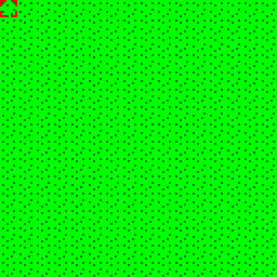
And now, when you assemble and run, you should see a grassy field like the image to the right. (Yes, it’s grass. I’m a programmer, not an artist.)
So from now on every function you write (except main) should look like this:
function_name:
push ra
    # code goes in between push and pop
pop ra
jr ra
If you still have a black screen at this point, STOP. STOP TRYING TO CODE WITHOUT BEING ABLE TO SEE ANYTHING. GET HELP. OHHHHHHH MY GODDDDDD WHY DO PEOPLE DO THISSSSSSS
There are a few possibilities for why the screen is still black:
- You didn’t do the
push ra/pop rastuff that I just explained in the previous section - If you did that right, and it is actually getting to the main loop, you may have passed the wrong arguments to
display_load_tm_gfxinload_graphics. - If that’s not it either, seriously, get help.
2. draw_cursor
Next we will draw the cursor, a little square frame to indicate which tile we are editing. We will draw it using a sprite, which is a movable image that is drawn on top of the tilemap.
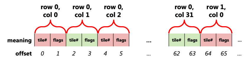
The way we put sprites onscreen is by storing values into the display_spr_table array. This is an array of bytes, where each sprite has 4 bytes of information. The bytes of the sprite table in memory look like this:
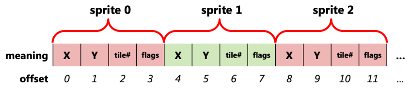
The “offset” at the bottom is what you add to the address of display_spr_table to get to that byte. You’ll be seeing that offset in the store instructions below.
Each sprite has a position (X, Y), a tile number (which image to draw), and flags which are options for the sprite. We won’t get into the flags too much in this lab, but setting flags to any number that ends in 1 will enable the sprite, causing it to appear onscreen. All the sprites start off disabled, and we only need one sprite for this program.
Here’s what you need to do:
- In the
.datasegment at the top of your program, declare two variables,cursor_xandcursor_yas.words, both initialized to 0. - Then in
draw_cursor, if you didn’t add thepush raandpop ratodraw_cursoralready, do it now. - Use
lato put the address ofdisplay_spr_tableinto some tttttttemporary register. (I’m usingt2below but you can use whatever t register you want. Just don’t usea, orv, orsregisters for this. They’re not aemporary or vemporary or semporary. They’re temporary.) - Set the sprite’s X position by:
- loading
cursor_xinto another temporary register - multiplying it by 8 in a single line, yes, you can do it, put the 8 in the
mul -
storing that value like so:
sb t0, 0(t2) # where t0 is cursor_x * 8, and t2 is the array address - The syntax
0(t2)looks super weird, but it means “the addresst2 + 0.” Yes. It’s addition. It’s a dumb syntax. But just look at the diagram above - offset 0 means the X coordinate of sprite 0.
- loading
- Do the same thing with
cursor_y- load it, multiply it by 8, but store into1(t2)- you should reuse the same temporary register for the Y value as you used for the X!
- Again,
1(t2)meanst2 + 1- that’s the offset of sprite 0’s Y coordinate.
- Store a zero byte into
2(t2)to pick tile 0. (Do you have a register that holds zero?) - Finally, store the constant
0x41into3(t2). REUSE THE REGISTER- We’ll come back to this in the future, but this will make it visible and color it red.
And when you run your program now, you should see a red box in the top-left!
If you don’t… well, here are your options:
- first, check that
load_graphicsis loading the sprite graphics. (Go back to this section, you are supposed to be doing two function calls in there) - a. plow ahead anyway, trying to implement
check_inputto move the invisible cursor around and having no idea if it’s working - b. bang your head against the desk for 6 hours trying to figure out what you did wrong while being super confused and feeling terrible
- c. ask me or a TA for help (it’s this one. this is the one you should do)
3. check_input part 1
Let’s make your program interactive. But we won’t be using the input syscalls anymore. Instead, we will be using the display’s built-in input facilities. It has both keyboard and mouse (trackpad) support, but we won’t look at the mouse until next lab.
Keyboard input works is through the display_key_pressed variable. The way you do it is a little odd:
- You store a number indicating the key you want to check into
display_key_pressed.- This tells the display which key you are interested in.
- You then load a value from
display_key_pressed. Yes, the same “variable.”- The loaded value is either 0 to mean “not pressed” or 1 to mean “pressed.”
- Repeat for any other keys you want to check.
It works like this because it’s a memory-mapped input/output (MMIO) location. We’re not interacting with memory, we’re interacting with the display through the store and load.
Exiting the program
In check_input, we want to check if the user hit the “escape” key, and if so, end the program. We will end the program not by using syscall 10, but by setting running = 0, which will cause the main loop to terminate when we get back there. (This is how most programs actually exit.) So:
- In
check_input, load the constantKEY_ESCAPEintot0, becauset0is like your dominant hand.- Do not write
li t0, 27. Writeli t0, KEY_ESCAPE. NAMES!!!!!!!!
- Do not write
- Use
swto storet0intodisplay_key_pressed. - Use
lwto loadt0fromdisplay_key_pressed. yes. reuse the same register. - If
t0 != 0…- Set the
runningvariable to 0.- Look at how
runningis declared to know which kind of store to use. - You can do this in one line.
- Look at how
- This is not an
if-else, just a simpleif.
- Set the
Now, run your program. It should stay running (the stop button should be green like this).
Then, click on the display to interact with it (like it says) and hit the escape key on your keyboard. Your program should stop and print -- program is finished running --. Woo! Interactivity!
If your program stops when you run it without you pressing escape, you probably got your if wrong. Remember:
- the label goes at the end of the
if, which is why I use the name_endif - think about when you want to skip the code in the
if, and write your branch to do that
Moving the cursor
Moving the cursor is similar. You are going to have multiple ifs in a row. These aren’t if-elses, just ifs. Here’s what you need to write after the if that you just wrote for escape, and guess what: you can write all of this code with only the t0 register. DO IT. GET USED TO IT!
Don’t use a switch-case for this. Use several ifs in a row. It’s important.
- if the user presses
KEY_LEFT, decrementcursor_x. - if the user presses
KEY_RIGHT, incrementcursor_x. - if the user presses
KEY_UP, decrementcursor_y. (Yes, decrement. Y increases downwards.) - if the user presses
KEY_DOWN, incrementcursor_y. - Note that you will have to name your labels differently for each
if.- Don’t number them. You are not a computer. NAME THEM. e.g.
_endif_L,_endif_R, etc.
- Don’t number them. You are not a computer. NAME THEM. e.g.
Now test your program. When you click on the display, you should now be able to move the cursor around with the arrow keys on your keyboard. Tapping the key just moves it one tile, and holding the key moves it continuously. (It might not move as fast as shown here, I just have my key repeat set really fast. But holding it down should move it continuously.) It should behave like the GIF below. If it doesn’t, you know what to do by now.

But there is one issue: if you move the cursor off any of the sides of the screen, it disappears. (If you hold it long enough, it comes back, but that’s not what we want.)
Limiting the cursor’s movement
The way we’ll solve this is with modular arithmetic. We’ll make it so the cursor “wraps around” when it goes off any of the sides. Doing this is extremely easy:
-
In all four
ifs, right before storing the value back intocursor_xorcursor_y, do this:remu t0, t0, 16 # the value IS in t0, RIGHT? - That will force
t0to stay in the range[0, 15]; if it tries to go below 0 it gets wrapped to 15, and if it tries to go above 15 it gets wrapped to 0. - (The use of
remuis important - theustands forunsigned. If you userem… well try it. Doesn’t quite work right.

4. check_input part 2 and place_tile
Now we’ll make it possible to place tiles into the tilemap. First, copy and paste these lines into your .data segment:
.eqv KEYS_LEN 4
keys_to_check: .word KEY_Z      KEY_X     KEY_C      KEY_V
keys_to_tiles: .word TILE_GRASS TILE_SAND TILE_BRICK TILE_WATER
These are two parallel arrays. Parallel arrays are one way of representing what we would use classes for in Java. Instead of having an “object” with multiple fields, we have multiple arrays, and each index in those arrays “go together” to describe one thing. So:
- They’re the same length. (The
KEYS_LENconstant is that length.) keys_to_check[0]andkeys_to_tiles[0]“go together.”- they mean “if
KEY_Zis pressed, place aTILE_GRASS.”
- they mean “if
keys_to_check[1]andkeys_to_tiles[1]also go together.- etc.
Now, here’s what you have to do in check_input, at the end of the function (after checking for left, right, up, down):
- Make a for loop using
s0as the loop counter that loops froms0 = 0tos0 < KEYS_LEN.- PUT. THE CONSTANT. IN. THE BRANCH.
blt s0, KEYS_LEN, _loop
- PUT. THE CONSTANT. IN. THE BRANCH.
-
Inside that loop, here’s what you need to do (notes follow):
display_key_held = keys_to_check[i]; if(display_key_held) { // 3 arguments... what registers do they go in? // when do you do that, before or after the jal? place_tile(cursor_x, cursor_y, keys_to_tiles[i]); }keys_to_check[i]-iis represented bys0here. What type of array iskeys_to_check? So what do you have to do with the index, and which load instruction do you use?display_key_heldis similar todisplay_key_pressed, except it tells you if the key is being held down. It works just likedisplay_key_pressedthough - store the key you want to check into it, then load a value from it, 1 means held, 0 means not held.- you have to index
keys_to_tiles[i]similarly tokeys_to_check. place_tileis another function that you are about to make!
The tilemap table
The way we change the tilemap is by storing values into the display_tm_table array. This is an array of bytes, where each grid square of the tilemap has 2 bytes of information. The tilemap is two-dimensional, and is 32 squares wide and 32 squares tall. The way this is represented in memory is like so:
Each tile is 2 bytes of data, so to move “right” by 1 column, you move over by 2 bytes.
Each row is 64 bytes, so to move “down” by 1 row, you move over by 64 bytes.
This gives us a formula for calculating the offset from the beginning of display_tm_table of any tile coordinate (X, Y), where X is the column and Y is the row: offset = Y * 64 + X * 2.
Okay. That’s the theory out of the way, and why we’re about to do what we’re about to do.
place_tile
- Make the
place_tilefunction. It’s a separate function. Do not put it INSIDEcheck_input.place_tiletakes 3 arguments.a0, a1are the tile X and Y respectively, anda2is the type of tile to store. You don’t have to “do” anything to get the arguments. You just writeplace_tileassuming the arguments are already ina0, a1,anda2.- What you can do though is document it with comments, like
 # a0 = x
 # a1 = y
 # a2 = tile type
 place_tile:
 push ra
     ...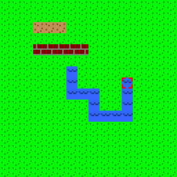
- Inside
place_tile:- calculate the offset using the formula from the previous section.
- X and Y are your
a0anda1!
- X and Y are your
- store a byte into
display_tm_tableat that offset
- calculate the offset using the formula from the previous section.
That should be it. Now to try it out:
- Move your cursor around and hit the Z, X, C, V keys. The tile under the cursor should change.
- Z places grass, X places sand, C places bricks, V places water. (yes it’s water shut up)
- You can hold down one of these keys, then hold an arrow to draw lines of that tile!
You’re breaking the law
One final thing: go back to check_input and look at your for loop. See how you’re using s0?
You didn’t ask for permission to do that. 😱
In order to “ask permission” to use an s register in any function EXCEPT main, you must push it at the beginning of the function and pop it at the end. So change the start and end of check_input to look like:
check_input:
push ra
push s0

...

pop s0 # <------- notice! BACKWARDS from the pushes!
pop ra
jr ra
Yeah it seems like nothing changed when you run the program, and it didn’t, this time. All that was happening was that you were getting lucky before.
Lucky and correct are not the same thing.
Small tangent: declarative design
The way we did the key checking in the previous part might have seemed a little odd to you. Why the heck did we have arrays of keys and tiles instead of just writing simpler ifs? Well, we invested a little bit more complexity up front (having to write the loop) for a more maintainable and modifiable program. See, these arrays:
.eqv KEYS_LEN 4
keys_to_check: .word KEY_Z      KEY_X     KEY_C      KEY_V
keys_to_tiles: .word TILE_GRASS TILE_SAND TILE_BRICK TILE_WATER
You can kind of just look at them and see what they do. Z puts a grass tile, X puts sand, etc.
Now, if we want to change the behavior of the code, we don’t need to touch the code at all. We just change these arrays. Want to use different keys? Want to swap which keys place which tiles? Want to add more keys to place other kinds of tiles? Just change the arrays, and the code doesn’t have to change!
This is a declarative way of writing code. Instead of hard-coding which keys place which tiles in check_input, we have more flexible code that reads what it’s supposed to do from the arrays. We simply “declare” what we want the code to do in the arrays. Abstraction.
5. load_map and char_to_tile_type
Okay, time to take the training wheels off and let you go figure these out.
First, copy and paste this array into your .data segment:
	map_data: .ascii
		"######          "
		"#    #          "
		"#..........     "
		"#..........     "
		"#    #   ..     "
		"######   ..     "
		"         ..     "
		"         ..     "
		"         ..     "
		"         ..   .."
		"         ..  .~~"
		"         ....~~~"
		"        .~~~~~~~"
		"       .~~~~~~~~"
		"       .~~~~~~~~"
		"       .~~~~~~~~"
This is actually a 16x16 array of bytes. Right? ;)
Now to write load_map:
void load_map() {
    // use s registers for row and col.
    // push and pop them at the beginning and end of this function.
    for(row = 0; row < 16; row++) {
        for(col = 0; col < 16; col++) {
            place_tile(col, row, char_to_tile_type(map_data[(row * 16) + col]));
        }
    }
}
Remember: write the code from the outside in, not top-to-bottom.
Also don’t get overwhelmed by that line inside the loop. Break it down. Think about the order of operations. It’s something like…
a0 = map_data[(row * 16) + col]; // BYTE array. break this down too!
char_to_tile_type();
a0 = col;
a1 = row;
a2 = v0; // return value from char_to_tile_type
place_tile();
Finally, what is char_to_tile_type? It’s this:
int char_to_tile_type(int ch) {
    switch(ch) {
        case ' ': return TILE_GRASS; // do NOT jr ra here.
        case '.': return TILE_SAND;  // ditto; see below
        case '#': return TILE_BRICK;
        case '~': return TILE_WATER;
        default:
            System.out.print("invalid character!\n");
            System.exit(0); // syscall 10
    }
}
Remember that to return a value from a function, you just put that value into v0. But then to actually exit the function, you need to jump to the pop ra line. If you don’t, the stack will get imbalanced and you’ll have a bad time!
If you get an error from char_to_tile_type about an invalid character, a common mistake is that you put the inner loop counter initialization before the outer loop. That is, you did something like:
    li s0, 0 # s0 = row
    li s1, 0 # s1 = column <------- THIS IS WRONG
    _row_loop:
        _col_loop:
when it should be:
    li s0, 0 # s0 = row
    _row_loop:
    	li s1, 0 # s1 = column <------- THIS GOES HERE!!!
        _col_loop:
Another possible cause of the invalid character error is that you are multiplying the row/column indexes incorrectly, possibly adding a multiply by 4 in there which you do not need.
If you get a black screen… well you’ve been there before. It’s probably stuck in an infinite loop, right? Diagnose it. See where it’s getting stuck. And if you can’t get it to work, get help.
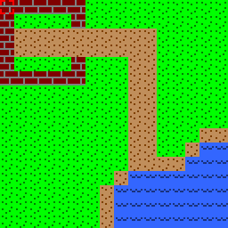
Done correctly, you should now see the map to the right loaded when your program starts. You can still move the cursor around and edit it. And you can edit the strings in the map_data array to edit what shows up when the program starts!
Submitting
Upload only your _lab6.asm file to Gradescope once it’s open.
Try This: Knowing what you know about functions now, go back to your lab 5 code. Move the various commands into their own functions and jal to them in each of the cases in main. Then, try making a draw_line function, and have both the line and rectangle commands use it. The program should still behave exactly the same way, but the code should be shorter and more readable!
Going further?
If you want to mess around with this more, go right ahead. Just don’t submit this stuff. Do this after submitting.
If you want to add another type of tile, here’s what you have to do:
- In
lab6_include.asm, add another tile’s graphics to the end of the array following the pattern of the existing tiles.- Each byte is 1 pixel. Each tile is 8x8 pixels.
- Colors
0x40through0x4Fare for backwards compatibility with the old display and their meanings are given in theCOLOR_constants above. - There are actually 256 colors available:
- colors 0x01 to 0x3F are a full, albeit small, palette
- colors 0x50 to 0x7F are all black.
- colors 0x80 to 0xFF are a gradual greyscale from full black to full white.
- In
load_graphics, increase the last argument (a2) todisplay_load_tm_gfxto 5.- or 6, or 7, or however many tiles you have.
- Increase the
KEYS_LENconstant, and add another entry to bothkeys_to_checkandkeys_to_tiles.- You’ll need this, which has the constants for all the keys that the display can handle. You can copy and paste the keys you care about into your program.
If you want to do more stuff… let me know and I’ll tell you how :D