Never skip a confusing step to “come back to it later.”
You probably learned to do this on exams, but this strategy does not work when building something. For example, when you’re building a house, you don’t “come back” to the walls after building the roof. YOU HAVE TO BUILD THE WALLS FIRST. Programming is no different. Things build on top of each other.
In this lab, you’ll be making the most awkward drawing program ever! (Don’t worry, next lab we’ll learn a much nicer way of getting input from the user.)
A note on autograding
The autograder is a dumb program. It is just programmatically feeding some inputs to your code and looking at the outputs. That means that if your program doesn’t perfectly match what the autograder expects, it marks it “wrong.” But that doesn’t mean it is wrong.
All actual evaluation and grading is done by a human. You should never trust what a computer says, and we don’t either. So don’t worry about if your submission is going to get a pointless 0 because it confused the autograder. There is a person at the wheel.
That being said, please try to make your prompt messages/outputs match my examples as closely as possible. It will make our job much easier because the autograder won’t be tripping over unexpected outputs, making us waste time by looking closely at a program that works fine but which the autograder couldn’t tell was okay.
Also if the autograder tells you to rename your file, rename it. Okay?
0. Getting started
-
Right-click and “save link” or “download link”, and put it in a new directory/folder for lab 5:
lab5_include.asmMake sure it really is saved as an
.asmfile and not.asm.txt! - In MARS, create a new file, and save it as e.g.
abc123_lab5.asmin the same directory that you put that include file.- but not literally named
abc123. Use your username. Like mine isjfb42, so I name itjfb42_lab5.asm.
- but not literally named
- Finally, in MARS, open the
lab5_include.asmand have a look.
What the heck is all this stuff?
First is a macro called lstr. Macros are common features in assemblers that let you specify your own “fake” instructions. When you use the macro, its contents are copied and pasted where you use it, in an intelligent way. I’ll explain how to use lstr later, but I would say don’t create your own macros unless you know what you’re doing.
Then there are some…
Named constants
All the .eqv lines define named constants. For example:
.eqv COLOR_BLACK       64
.eqv COLOR_RED         65
.eqv COLOR_ORANGE      66
The Java equivalent would be something like:
public static final int COLOR_BLACK  = 64;
public static final int COLOR_RED    = 65;
public static final int COLOR_ORANGE = 66;
These are named constants. Named constants are wonderful. Names are wonderful. Whenever you have some “magic value” that has specific importance, don’t write it inside your code. Make a named constant for it.
These are not variables. You do not use lw with them. Instead, you can use them anywhere a constant is normally written (like in li, or as the last operand to an add, or as the second operand in a beq, etc.).
Also, don’t just write the value of the named constant when you need it. Use the name!:
| Mysterious | Obvious |
|---|---|
|
|
Why do we do this? Not only is it more readable, it means we can change the value of the constant in the future, and none of the code that depends on it has to be changed. Every use of that value will be changed across the whole program, all at once.
After the named constants are…
The MMIO variables
Syscalls are one way of making our programs interact with the real world. But another way is by accessing the hardware directly with memory-mapped input and output, or MMIO for short.
Normally, loads and stores copy data between the CPU and RAM. But with MMIO, certain “magical” addresses refer to other hardware devices than RAM.
When you access memory at these “magical” addresses, the data is transferred between the CPU and the hardware device, instead of between the CPU and RAM. The CPU thinks it’s accessing memory, but the data is instead intercepted and sent to/received from another device instead.
With MMIO, a load (lw) becomes a general-purpose “get a value from a device” instruction, and a store (sw, sb) becomes a general-purpose “send a value to a device” instruction. That’s it.
Now, you don’t have to know anything about the variables in lab5_include.asm, and you should not use these variables directly. Instead, you should use…
The driver functions
These are the only way you should interact with the display. Have a look at their code. Notice that they are doing loads (lw) and stores (sw, sb) into those MMIO variables. They’re communicating with some “piece of hardware.” So what exactly are they controlling?
Our imaginary hardware device, the Display
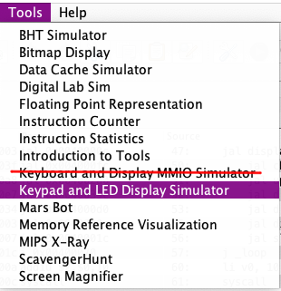
In MARS, go to to Tools > Keypad and LED Display Simulator. Not Keyboard and Display MMIO Simulator. This will pop up a window. Click the “Connect to MIPS” button in the bottom left.
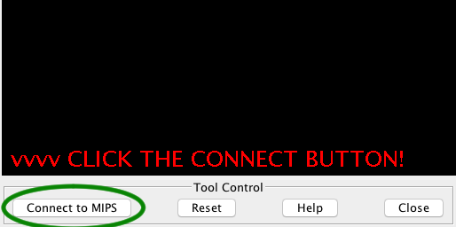
Once it’s connected, you don’t have to close the window or reconnect it. You can re-assemble and re-run your program as many times as you want while the display is open. I mean, yeah, it might be awkwardly in the way so you can close it, but… I’m just saying you don’t have to close it and reopen it every time you run your program.
How the display works
- The display is 128 pixels wide by 128 pixels tall.
- Each pixel can be one of 256 colors, numbered 0 through 255, but there are also named constants for some of these colors in
lab5_include.asm.
- Each pixel can be one of 256 colors, numbered 0 through 255, but there are also named constants for some of these colors in
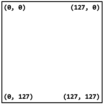
- The origin (0, 0) is at the top-left.
- The X axis increases to the right, and the Y axis increases down.
- You can see how this works in the image to the right.
- (This is typically how graphical displays are arranged and accessed, because they grew out of text displays, where this arrangement is natural, as text starts at the top left, and also because CRT displays drew everything top-to-bottom left-to-right like this.)
- The pixel data is stored in a 2D array in memory. You won’t be accessing this array directly, but it means there are two steps to displaying stuff:
- Draw as many pixels as you want using the provided
display_set_pixelfunction; then - Use the provided
display_finish_framefunction to copy the data from memory to the screen.
- Draw as many pixels as you want using the provided
- You can think of it like drawing on a piece of paper, and then when you’re done with the drawing, you give it to someone and they stick it to the fridge for everyone to see.
display_set_pixelis “drawing on the paper,” so you keep calling it to draw as many dots as you want.display_finish_frameis “sticking it on the fridge for everyone to see,” so you do it once after drawing all the dots that you want to. display_finish_framealso limits the display’s framerate to 60 FPS (60 frames per second) in this lab. So if you call it really often, it will actually slow down your program.
.
.
.
.
.
.
Keep scrolling…
.
.
.
.
.
.
.
.
.
.
.
.
.
.
.
.
.
.
.
.
.
.
.
.
.
.
.
.
.
.
.
.
.
.
.
.
.
…just a little further…
.
.
.
.
.
.
.
.
.
.
.
.
.
.
.
.
.
.

You didn’t just… scroll all the way down here without reading all the stuff up top, did you? No, you wouldn’t do that! Surely you wouldn’t skip reading all the incredibly important fundamental information I wrote so that you wouldn’t be super confused about everything. :)))))))))
1. Getting the display going by calling a function
So far you have only done system calls, which call functions in the fake “operating system” to do input and output. But you can call regular functions as well. The instruction to do this is jal, which stands for jump and link. (We’ll learn why soon.)
The display can operate in two modes: classic mode, which is backwards compatible with all the assignments I’ve given for the past, like, 5 years; or enhanced mode, which has a bunch of new features we’ll be making use of.
We have to do some special stores into some of the MMIO addresses in order to make the switch. That’s what the display_init function does for us.
Importantly, the display must already be open and connected to MARS before calling display_init, or else it will not switch into the new enhanced mode. So:
-
In your
_lab5.asmfile, put this at the top (right after your name/username):.include "lab5_include.asm"- this will make all that stuff in the
lab5_include.asmfile available to your program.
- this will make all that stuff in the
- Make your
mainfunction as usual. -
In
maincalldisplay_initby writing:jal display_init- Yeah, calling normal functions is a lot nicer because you get to use their names.
- Save and assemble your program, but do not run it yet.
- Make sure the display window is open and connected.
- Run your program.
It might not look like much happened, but look at the top of the display:

It should now say “Enhanced Mode!” So those weird sws in display_init did their job.
# oh what's that? you can't select
# this code? oh noooo guess you'll
# have to type it yourseeeeeelf :)
main:
    jal display_init

_loop:
    # print the command message
    # read a string from the user
    # branch to appropriate label
    # jump to _break
_pixel:
    # code goes here
    # jump to _break
_color:
    # code goes here
    # jump to _break
...etc...
_quit:
    # do the exit syscall
_break:
    # jump back to _loop
2. The main loop
If you’re starting this lab before the control flow lecture, you might be a bit confused, but maybe you should try jumping into the pool anyway. I can’t hold your hand through everything.
After calling display_init, put a _loop: label. This is going to be the start of our main loop. Make sure you name all your labels starting with an underscore. It might look a little funny, but this will be important once we start writing multiple functions.
You are about to build a switch-case (click this link). Your code is not going to look completely identical to that, but it will have a similar structure. In the code sketch to the right, _pixel, _color, and _quit are the case labels.
For printing strings, I’ve given you the lstr macro to make it easier. Here’s how you use it:
    lstr a0, "this is a message to print!\n"
    li v0, 4
    syscall
Now you don’t have to go through the trouble of making all those variables, because lstr does it for you. (And you can like, see the string that you’re printing where you’re printing it)
For asking the user for string input, you did that on lab 1 already with syscall 8, so do the same thing again here. But after doing syscall 8, you have to get the first character out of the string so that you can switch on it. Here’s how you’ll do that:
    # this is what you learned to do on lab 1.
    la a0, input_buffer
    li a1, 10 # or whatever length you made it
    li v0, 8
    syscall

    # get first character of input_buffer with lb (load *byte*) and switch on it
    lb t0, input_buffer
    beq t0, 'c', _color # single quotes!
    # etc...
Now you need to make your program behave like this (and read the notes after):
Command ([c]olor, [p]ixel, [l]ine, [r]ectangle, [q]uit): c
<color unimplemented>
Command ([c]olor, [p]ixel, [l]ine, [r]ectangle, [q]uit): p
<pixel unimplemented>
Command ([c]olor, [p]ixel, [l]ine, [r]ectangle, [q]uit): l
<line unimplemented>
Command ([c]olor, [p]ixel, [l]ine, [r]ectangle, [q]uit): r
<rectangle unimplemented>
Command ([c]olor, [p]ixel, [l]ine, [r]ectangle, [q]uit): x
Command ([c]olor, [p]ixel, [l]ine, [r]ectangle, [q]uit): q

-- program is finished running --
- The
c,p,l,rcommands should display a message saying that they are unimplemented.- Each one should have its own message. That means each one has its own label.
- Name your labels sensible things, e.g.
_pixel, not_por_labelor something.
qshould quit (syscall 10).- Only
qshould quit - the program should never exit in the other cases.
- Only
- Any other letter should ask for another command, because it loops.
- Please make your prompts and outputs match the above.
- This will make grading easier.
- You can put
\nat the end of a string to move to a new line, like"<color unimplemented>\n"
You have to get this working correctly. This is the foundation for the rest of your program. If this doesn’t work right, the rest of the program won’t work right either.
3. The pixel command
The p command should work like this:
Command ([c]olor, [p]ixel, [l]ine, [r]ectangle, [q]uit): p
Enter X coordinate: 10
Enter Y coordinate: 20
Command ([c]olor, [p]ixel, [l]ine, [r]ectangle, [q]uit):
And that should cause the display to change like so:

WOw!!!!!!!!!! (if your display is dim, click on it. That “Click here to interact” message dims the display. We’ll be using the display’s own input stuff next time.)
Remove the <pixel unimplemented> message from this command when you implement it. That goes for every command.
Here’s what you need to know:
- just like on lab 1, you might have move each integer into a sssssssafe place.
- alternatively, you could store each one in a variable. variables are safe too!
- then later when drawing the dot, you’d load their values.
- the function you call to draw a dot is
display_set_pixel. it takes three arguments:a0is Xa1is Ya2is the color to use- use
COLOR_WHITEfor this. not 71,COLOR_WHITE.
- use
- you have to put these values in the
aregisters before doingjal display_set_pixel. code is executed from top to bottom.display_set_pixelcan only see what you already put in the argument registers.
- finally, after calling that, you need to call
display_finish_frameto “put the drawing on the fridge”.- It takes no arguments. Just
jal display_finish_frameis all you need. - If you don’t call this, nothing will show up on the display!
- It takes no arguments. Just
4. The color command
The color command lets the user choose the color to draw in. Here’s how it should work:
Command ([c]olor, [p]ixel, [l]ine, [r]ectangle, [q]uit): c
Enter a color in the range [0, 15]: -1
Enter a color in the range [0, 15]: 16
Enter a color in the range [0, 15]: 5
Command ([c]olor, [p]ixel, [l]ine, [r]ectangle, [q]uit):
Importantly, if the user enters something less than 0 or greater than 15, it should ask again. So how do we check that? Well there are actually a whole family of branch instructions, one for each kind of condition you can check:
| Instruction | Read as… | Operation |
|---|---|---|
beq a, b, _label |
“branch if equal” | if(a == b) jump to _label; else go to the next line |
bne a, b, _label |
“branch if not equal” | if(a != b) jump to _label; else go to the next line |
blt a, b, _label |
“branch if less than” | if(a < b) jump to _label; else go to the next line |
ble a, b, _label |
“branch if less or equal” | if(a <= b) jump to _label; else go to the next line |
bgt a, b, _label |
“branch if greater than” | if(a > b) jump to _label; else go to the next line |
bge a, b, _label |
“branch if greater or equal” | if(a >= b) jump to _label; else go to the next line |
You can put numbers in the branches! Idk why so many people miss this! It saves you so much time! Examples:
beq t0, 0, _its_zero

beq t0, COLOR_WHITE, _its_white # constants are numbers too!

blt t0, 128, _its_under_128 # any kind of branch can do it!
Now, what should we do with the number that they type in? Well:
- Make a
colorvariable. It should be a.wordand be initialized toCOLOR_WHITE. - After checking that the color they entered a valid color in the range [0, 15]:
- add
COLOR_BLACKto that number to put it in the range [64, 79]- remember, put the constant name in the
addinstruction. don’t uselior64.
- remember, put the constant name in the
- store it into
color
- add
- Change your
pcommand code so that instead of usingCOLOR_WHITEfora2, it loads thecolorvariable intoa2.
Now, you should be able to change the color and put pixels of multiple colors onscreen. 1 is red, 2 is orange, 3 is yellow, 4 is green, 5 is blue, etc. Look, I drew the tiniest piece of a rainbow! It was a huge pain! lol

5. The line command
The line command draws horizontal lines in a single color. A line is a bunch of dots in a row. Here’s how it should work:
Command ([c]olor, [p]ixel, [l]ine, [r]ectangle, [q]uit): l
Enter X coordinate: 10
Enter Y coordinate: 20
Enter width: 100
Command ([c]olor, [p]ixel, [l]ine, [r]ectangle, [q]uit):
And it should draw a line 100 pixels wide, starting at (10, 20), in whatever color the user entered with c:

(Don’t worry about invalid widths. We won’t give your program any.)
How you write this is up to you. You will definitely need:
- a loop, which is controlled by…
- a loop counter that loops from
xtox + width; and you need… - to keep the X, Y, and width values somewhere safe; and finally:
- to call
display_finish_frameafter the loop to make the line visible.- you could actually call it in the loop, to see the pixels being drawn one by one, but…
- it makes the line take forever to draw!
For all the values involved here (loop counter, X, Y, width), you could either use variables or s registers. It’s up to you.
Also, don’t forget to use the current color as the a2 argument to display_set_pixel.
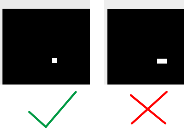
Making sure you don’t have an off-by-one error
An easy mistake to make is to draw your lines one pixel too long. That’s an off-by-one error. To check, try drawing a line at (10, 10) that is 1 pixel wide. You should see a single pixel turned on, not a tiny rectangle (you can use the “Zoom” checkbox at the top of the display to zoom in on it). That is,
6. The rectangle command
The final boss. A rectangle is just a bunch of lines on top of each other. Here’s how it works (I’m just changing the color cause I’m bored of white; color 5 is blue):
Command ([c]olor, [p]ixel, [l]ine, [r]ectangle, [q]uit): c
Enter a color in the range [0, 15]: 5
Command ([c]olor, [p]ixel, [l]ine, [r]ectangle, [q]uit): r
Enter X coordinate: 30
Enter Y coordinate: 40
Enter width: 50
Enter height: 60
Command ([c]olor, [p]ixel, [l]ine, [r]ectangle, [q]uit):
And it will draw a 50x60 rectangle, with the top-left corner at (30, 40):

For this one, I would really recommend you store the Left, Top, Right, and Bottom (see below) in variables rather than using s registers. Once you start getting this many values, having s0, s1, s2, s3, s4, s5 etc. it gets really hard to tell what the hell the code is doing. Variables have names, which make the code more readable:
    lw t0, right       # see, a name!
    blt s0, t0, _xloop # now we can see that t0 holds right
Left and Top: X and Y are kind of nondescriptive names for a rectangle, so I’d recommend naming the variables for the rectangle’s X/Y coordinates left and top or similar.
Right and Bottom: rather than storing the width and height of the rectangle, it will make your code much simpler if you keep track of right = left + width and bottom = top + height. That way, the loops in your code will just have to test if the loop counter is less than right/bottom.
Some pseudocode: since this is probably going to be pretty tricky for many of you at this point, here is some Java-like pseudocode for what you need to write:
    // x is a loop counter; an s register is a very good choice for it.
    // `left` is what the user typed in.
    int x = left;

    // load `right` into a register *right before* this branch. you *cannot* stick a variable
    // in a register and use the register in place of the variable throughout the code.
    while(x < right) {
        // y is another loop counter. another s register. `top` is what the user typed in.
        // it's SUPER IMPORTANT that you put this initialization inside the outer loop.
        int y = top;

        // again, load `bottom` right before this branch.
        while(y < bottom) {
            display_set_pixel(x, y, color);
            // the increment is the *last* thing in the loop
            y++;
        }

        x++;
    }

    // don't forget!
    display_finish_frame();
If your rectangle comes out looking like this:

Then you didn’t put the y = top inside the outer loop. You put it before the outer loop.
Whew!
Off-by-one, again
Once again, you should test that drawing a 1x1 rectangle only turns on a single pixel.
Submitting
First, be sure to test your program thoroughly.
- does it loop infinitely until you exit with
q? - can you draw a pixel with
p? - can you change the drawing color with
c?- does it properly ask you again if you enter a color < 0 or > 15?
- can you draw a line with
l? - how about a rectangle with
r?- if not, does it display a message saying it’s unimplemented?
- does any unrecognized command (e.g.
x) just ask for a command again?
Then, you can submit. Upload to Gradescope, once it’s open.
The last submission you upload is the one we grade.