You will make a circuit capable of adding or subtracting two 4-bit numbers. It will also be able to detect overflow for both the unsigned and signed interpretations of those two operations.
To make things interesting, you are only allowed to use a single adder component. It’s, uh, realistic!
1. Getting started
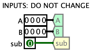
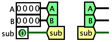
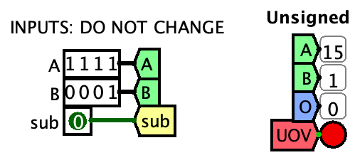
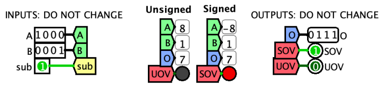
Download this file, rename it to your username, and open it in Logisim (File > Open). You’ll see this:
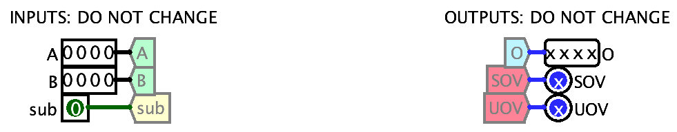
Similar to the previous lab, the inputs and outputs will be used to hook your circuit up to an autograding circuit, so do not change any of them. (Well, you can change the inputs’ values, but don’t move them around, rename them, etc.)
The colorful shapes attached to the inputs and outputs are…
2. Tunnels
Tunnels are a way of naming wires, and let you connect things over long distances without having to use really long wires. You may have run into problems in lab 1 where the wires had to cross over each other and go long distances in ugly ways. Tunnels let you solve that.
Just like in Java, tunnels names are case-sensitive. Here, we have A and B. a and b would be different tunnels.
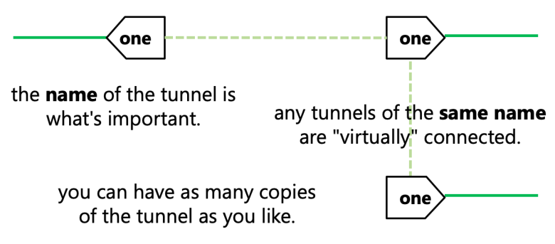
Right now the tunnels are gray, which means they have no “partners.” Let’s give them some partners:
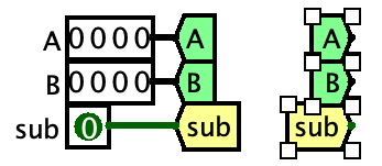
- Select just the three tunnels named
A,B, andsuband hit Ctrl+D/⌘D to Duplicate them.- You will now see “ghosts” of the tunnels that follow your mouse.
- Move the “ghosts” to the right of the inputs, and click to place the duplicates there.
- (Copying and pasting works the same way (Ctrl+C/⌘C to copy, Ctrl+V/⌘V to paste)).
- Notice that the tunnels are no longer gray! They have partners.
- With the new copies still selected, hit the right arrow key on your keyboard.
- This will make them face right.
- (Try hitting the other arrow keys. Whee!)
- If this doesn’t make them face right: let me know, it works for most people but occasionally it doesn’t and idk why, and maybe you can help me fix the bug
- You should now have what’s in the picture on the right.
- This will make them face right.
- With the arrow (edit) tool, click and drag on the little black dots on the right sides of the three new tunnels to create some wires like you see on the right.
- With the hand tool, poke some of the bits in the
AandBinputs to change them. Then poke the wires coming out of the inputs, and the new wires that you just made.- Poking a wire lets you see what value is being carried by it.
- By default, it shows the value as
Binary / Signed Decimalbut that can be changed with File > Preferences > Layout > First/Second radix when wire poked.
3. Probes
Poking wires to see their values is sometimes useful but often tedious. So instead, let’s use probes.
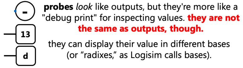
Now we’re gonna make this thing.
- Delete your duplicated
subtunnel and replace it with a duplicatedOtunnel instead (from the outputs). - In the parts library on the left, open the Wiring folder, click Probe, and click on your circuit to place it at the end of the wire as shown. Then make 2 more the same way.
- If your probes look like this, they’re not hooked up right.
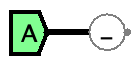
- See the little dot on the right side of the probe? That is the pin that has to be connected for it to work.
- Select the probe, then hit the left arrow key to make it face left, then connect it to the tunnel.
- If your probes look like this, they’re not hooked up right.
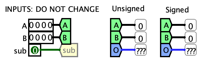
- Select all three probes that you just made and set their Radix property to Unsigned Decimal.
- Select the whole mess, duplicate it, and set the duplicated probes’ Radix to Signed Decimal.
- Use the text tool to label the left column “Unsigned” and the right column “Signed” to make it easier to read.
Now you can see what values are being added/subtracted, and what the result is, in both the unsigned and signed interpretations! Try changing the values of the A and B inputs and you’ll see the probes’ values change.
Probes are just a debugging tool. They do not have any effect on the circuit, and cannot be used in place of outputs.
Wire colors, blue wires, and x/???
You can already see several wire colors going on: black, two shades of green depending on what the sub input is, and blue. Also, the probes for O are displaying ???. What’s going on?
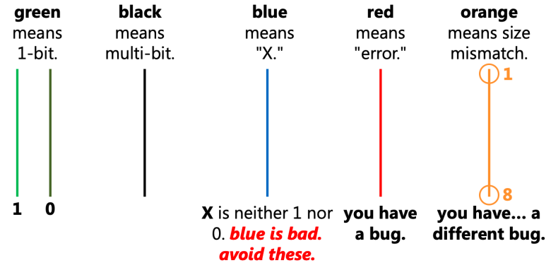
The O wire is not being given a value by any component, so it has the value of X. That’s why it’s blue, and that’s why the probe is showing ???. We’ll fix that soon.
4. The basic adder
Now to make some real circuitry. You’re going to be building the thing on the right.
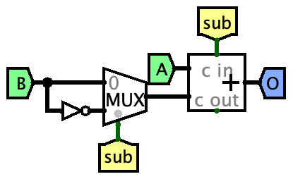
- Place the following components into your circuit:
- One adder from the “Arithmetic” folder
- Set its Data Bits property to 4
- One NOT gate
- Set its Data Bits property to 4
- One multiplexer from the “Plexers” folder
- Set its Data Bits property to 4
- Leave Select bits at 1
- Duplicate the
Otunnel again and make it face left as shown
- One adder from the “Arithmetic” folder
- Connect things up like the image to the right by using the arrow tool to draw wires between things.
- To make a wire junction (the thick black circle on the left), just click in the middle of a wire and drag away from it. It’ll create a new wire connected to it.
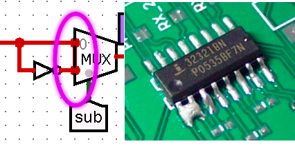
- Watch out for “solder bridges.” This is when two or more pins of a component are joined together by “hidden” wires. You can see them as those “wire junction” circles on the pins. (This is a problem in real life, too.)
- Now test it!
- Switch to the hand tool (Ctrl+1/⌘1) and poke the 0s and 1s in the inputs. Watch the inputs and output change on the probes.
- Switch between addition and subtraction with the
subinput.- See how it’s hooked up to the adder’s carry in, so that when
subis 1, it makes the adder add the extra 1 when subtracting?
- See how it’s hooked up to the adder’s carry in, so that when
A note on super-long wires and tunnels
New users of Logisim often make circuits like this.
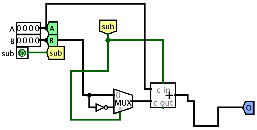
Just like you can have spaghetti code, you can also have spaghetti circuits. This is extremely hard to read and understand.
To avoid spaghetti circuits, follow these two rules:
- When you need a value that comes from a tunnel, do not draw a long wire from an existing tunnel. Instead, duplicate (or copy and paste) the tunnel where you need it. That is the whole point of tunnels - so that you can use values wherever you need them!
- Keep your wires as short and straight as possible.
Logisim can also help you straighten out your wires. See the wire coming out of the adder going on a long journey to the O tunnel? To fix this, just move the O tunnel around a bit and Logisim will straighten the wire. As you move it closer to the adder, the wire gets cleaner and cleaner until it’s a nice short straight wire.
5. Detecting unsigned overflow
Unsigned overflow happens if we’re adding (sub == 0) and the carry out from the adder is 1; OR if we’re subtracting (sub == 1) and the carry out is 0. If we make a truth table (remember, the sub and c out columns correspond to your sub tunnel and the c out from the adder):
| sub | c out | UOV |
|---|---|---|
| 0 | 0 | 0 |
| 0 | 1 | 1 |
| 1 | 0 | 1 |
| 1 | 1 | 0 |
This can be done with a single gate! (Go look at your notes on gates, and look for the truth tables for the basic kinds of gates. You can find this gate in the “Gates” folder on the left.)
Let’s see if you can do it on your own now. Your goal is the picture on the right. Duplicate tunnels as needed (UOV is connected to one of the outputs). The red circle is an LED from the “Input/Output” folder. Test that it properly detects overflow for both subtraction and addition.
6. Detecting signed overflow
First, you need to get the sign bits of the operands and output. Your goal is to build the image on the right. Here’s how:
- Splitters can take multi-bit wires and split them into single bits.
- Make a Wiring > Splitter and set its properties like so:
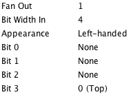
- This will make something that looks like a little laser gun with a
3on it.- The black side of the splitter accepts a 4-bit number.
- The green side will output bit 3 (the MSB) from that 4-bit number.
- Make a Wiring > Splitter and set its properties like so:
- Now copy and paste that splitter a couple times for a total of three splitters.
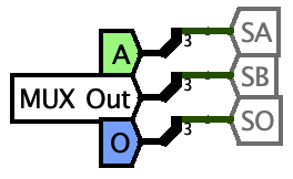
- Make a new tunnel named
MUX Outconnected to the output of the MUX- that wire carries either
Bor~B, depending onsub.
- that wire carries either
- To the input (black) side of the splitters, connect the
A,MUX Out, andOtunnels.- Make copies. Don’t just make long wires from existing tunnels. That defeats the purpose of them!
- To the output (green) side of the splitters, make and connect some new tunnels named
SA,SB, andSOfor the sign ofA, the sign ofMUX Out, and the sign ofOrespectively.
| SA | SB | SO | SOV |
|---|---|---|---|
| 0 | 0 | 0 | 0 |
| 0 | 0 | 1 | 1 |
| 0 | 1 | 0 | 0 |
| 0 | 1 | 1 | 0 |
| 1 | 0 | 0 | 0 |
| 1 | 0 | 1 | 0 |
| 1 | 1 | 0 | 1 |
| 1 | 1 | 1 | 0 |
Now you have three tunnels, SA, SB, and SO which carry just the signs of the two addends and the output. You can then copy and paste those tunnels to use them as inputs to the circuit you are about to build.
Using the method to turn a truth table into a boolean function that you learned last lab, turn this truth table on the right into a real circuit. The inputs are the tunnels you just made, and the output will be the SOV tunnel that is connected to the SOV LED.
Be sure to test all 8 possible combinations of signs (two inputs and one output) for addition! Then do it again for subtraction! For 4 bit signed numbers, the range is [-8, +7] and computing any number outside that range should turn on the SOV LED. For example below, I am computing -8 - 1, which would be -9, but we can’t represent that, so we get a signed overflow.
Submitting
You will submit on Gradescope. It will test your circuit pretty thoroughly.
But before you submit… To save yourself some time and a headache, make sure your overflow circuits are actually connected to the UOV and SOV tunnels, not just to the LEDs.
If your outputs look like this, the autograder will just give you a 0 on the overflow parts:
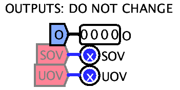
If you didn’t do so already, duplicate the UOV and SOV tunnels and connect them to the outputs of your overflow circuits.