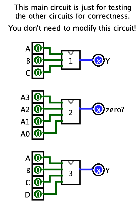
In this lab, you will be getting practice building circuits in Logisim, reading boolean functions, and turning truth tables into circuits.
To do this lab, you must have completed Lab 0 and have Logisim installed and working on your computer. If you didn’t do that yet, do it now.
0. Getting started
Download this file and rename it to have your username instead of abc123. Then open it in Logisim.
You cannot double-click the file to open it in Logisim (womp womp). Instead, you have to run Logisim, and use File > Open to open it. I know it sucks.
When you do, you’ll see this:

If everything is really tiny, don’t forget that you can zoom in with the zoom control in the bottom-left corner of the window.
1. Circuit 1
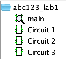
Look at the component panel on the left. You’ll see main, and under it, Circuit 1, Circuit 2, and Circuit 3 (as shown in the image on the right).
The magnifying glass 🔍 on main means that is the circuit we are currently editing. You can see the stuff in the middle - those are circuits 1, 2, and 3, but placed as components within the main circuit.
Now, double-click Circuit 1’s name in the component panel on the left. The magnifying glass will switch to it, and the circuit diagram will change:
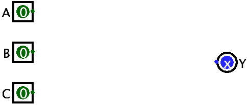
On the left, the boxes labeled A, B, C are the inputs to this circuit.
On the right, the circle labeled Y is the output from this circuit.
Your job is to place gates and draw wires to implement the following boolean function:
Remember:
- Adjacent variables like \(AB\) are ANDed together
- The \(+\) sign means OR, not AND!
- The bar over a variable means NOT
There is also an order of operations for boolean functions: NAO. NOT first, then AND, then OR last. This has implications for the way you arrange your gates: a NOT gate on the input of an AND gate does something very different from a NOT gate on its output!

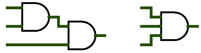
Also, if you end up with NOT gates that look like the right: you can’t just plop a NOT gate on top of a wire. You can “un-draw” the wire by clicking on the input of the gate and dragging to the output.
Once you believe you have implemented the circuit correctly, you can use the hand tool to poke the A, B, C inputs and verify correctness against this truth table:
| A | B | C | Y |
|---|---|---|---|
| 0 | 0 | 0 | 0 |
| 0 | 0 | 1 | 0 |
| 0 | 1 | 0 | 1 |
| 0 | 1 | 1 | 1 |
| 1 | 0 | 0 | 1 |
| 1 | 0 | 1 | 0 |
| 1 | 1 | 0 | 1 |
| 1 | 1 | 1 | 0 |
Look back at the boolean function and compare it to the truth table. Does it make sense? Like, what does “not A and B” mean and how does that show up in the truth table?
2. Circuit 2
Don’t forget to save.
Often in computing we need to check if some number is 0. Circuit 2 will be a “zero detector.” You can imagine that the 4 inputs are the bits of a 4-bit number. Circuit 2 will output 1 if all 4 inputs are 0, and 0 otherwise.
There is more than one way to do this! I’m letting you figure it out for yourself. But, something good to know that might be helpful: gates can have more than 2 inputs. Below is an image of 2 circuits that behave identically. The left one ANDs three bits together (it only outputs a 1 if all inputs are 1). The left one does the same, but it does it with a single gate symbol.
To do this: make a gate. Click it, and look at its properties on the left. Change its Number of Inputs property to add more inputs. You can also change its Gate Size property if you think it looks funny with the little “wings” on it. This works for any multi-input gate (e.g. AND, OR, XOR).
To test this circuit: well try every combination of inputs. It should only output a 1 when all of them are 0.
3. Circuit 3
For this circuit, you’ll turn this truth table into a circuit (keeeeep reading after it):
| A | B | C | D | Y |
|---|---|---|---|---|
| 0 | 0 | 0 | 0 | 0 |
| 0 | 0 | 0 | 1 | 0 |
| 0 | 0 | 1 | 0 | 0 |
| 0 | 0 | 1 | 1 | 1 |
| 0 | 1 | 0 | 0 | 0 |
| 0 | 1 | 0 | 1 | 1 |
| 0 | 1 | 1 | 0 | 0 |
| 0 | 1 | 1 | 1 | 0 |
| 1 | 0 | 0 | 0 | 0 |
| 1 | 0 | 0 | 1 | 0 |
| 1 | 0 | 1 | 0 | 0 |
| 1 | 0 | 1 | 1 | 0 |
| 1 | 1 | 0 | 0 | 0 |
| 1 | 1 | 0 | 1 | 1 |
| 1 | 1 | 1 | 0 | 0 |
| 1 | 1 | 1 | 1 | 1 |
Wow that’s a big ugly thing. And uh…
How do you turn a truth table into a circuit?
Often we don’t start with a boolean function, but with a truth table instead. A truth table describes a Boolean function, but doesn’t actually say how to build it.
The problem is, for any truth table there is an infinite number of Boolean functions which could correspond to it. So, we need some kind of technique, or algorithm, which we can feed a truth table and it will produce a Boolean function.
One way of reading a truth table is like an “if-then” statement. Let’s look at this little table:
| A | B | Y |
|---|---|---|
| 0 | 0 | 0 |
| 0 | 1 | 1 |
| 1 | 0 | 1 |
| 1 | 1 | 0 |
The second row can be read: “if A is 0 and B is 1, then output a 1.” A more “logical” reading is “if NOT A AND B, then output a 1.” Hey, that looks more like logic!
Every row in the truth table can be read this way, but for our purposes we only care about the rows where the output is a 1. This technique isn’t particularly smart, but it will work, every time. It goes like this:
- For each row where the output is a 1:
- AND together all the input variables, but put NOTs on any inputs that are 0 in that row.
- OR together the outputs of all the ANDs.
- The output of the OR is the output of the truth table.
- You can write the function like
Y = ...where the...is the stuff you did in steps 1 and 2.
- You can write the function like
That’s it.
Now try doing that to the table above on paper. You are going to get a Boolean function with:
- two NOTs
- two ANDs
- one OR
Do it with a partner and compare your answers. Did you get the same thing? You can also try building it in Logisim to test that the function you made matches the truth table. You can make a new file, and switch between that file and your lab in the Window menu.
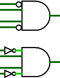
Now do it to the big 4-input truth table. One more feature that might be useful here: in addition to having multiple inputs, gates can also have “built-in NOT gates” by using the Negate Input properties. On the right are two equivalent circuits: the top one has inputs 1 and 4 negated, while the bottom one uses separate NOT gates. It’s up to you!
Submitting
Yes I know the gradescope is not up yet just chill
Submit on Gradescope. It will test your circuit pretty thoroughly.